Setting up CDN
This article will teach you how to streamline the delivery of a video content to other continents. The video content is both live video restreamed from the ingest servers and video stored on HDD (e.g. DVR or VOD) at origin servers.
The main problems with the delivery of such a content over long distances via the public Internet are:
- Instability. The signal goes through a lot of routers to get from an ingest/origin server to the end user while the stability of data transmission is not guaranteed on that path. It may take dozens of seconds before the user receives the requested video.
- Costs. The channels between continents, countries, or regions are usually more expensive than local/city channels so referring distant users directly to ingest/origin servers is quite unprofitable.
- Load. A simultaneous video request by a large number of users can overload your server.
This problems are usually solved with a CDN (Content Delivery Network). It is a set of servers with specialized software that are physically located in regions where the users access your content. You may fully duplicate or cache the DVR content on the local CDN servers and distribute the live playback sessions between them. This mechanism significantly speeds up the content delivery and distribution to the end user, reduces the cost of communication channels and optimizes the load on the servers.
Flussonic has a number of features to simply implement a CDN of any scale. The use of Flussonic as the specialized software on CDN servers provides a number of advantages, for example:
- The built-in caching mechanism designed for video delivery with personalized advertising (see also Content monetization using ad insertion).
- You don't have to send several protocols to the edge servers via expensive channels because Flussonic on the edge server will pack the video into the required format.
In this article, we will consider an example of a small CDN broadcasting live shows.
Below you will find configurations of all servers in the video pipeline, from ingest to edge (CDN). If you are only interested in CDN, please refer directly to Distribution.
The pipeline
The pipeline structure will be as follows:
- In the capture region, there will be at least two redundant servers.
- In the region of broadcasting, the servers will ingress video from one of the two sources.
- Each channel will be transmitted between the regions only once, to keep the intercontinental traffic to minimum.
- In the capture region, video will be transcoded and recorded in order to prevent losses in case of channel outage.
In the examples below, each server will perform a certain role like ingest and transcoding, recording, distribution. You can combine the servers in the capture region in any way you want depending on the hardware resources available, for example, ingest, transcode and record on the same server. The diagram below shows the video streams in the proposed system, dotted arrows indicate backup channels.
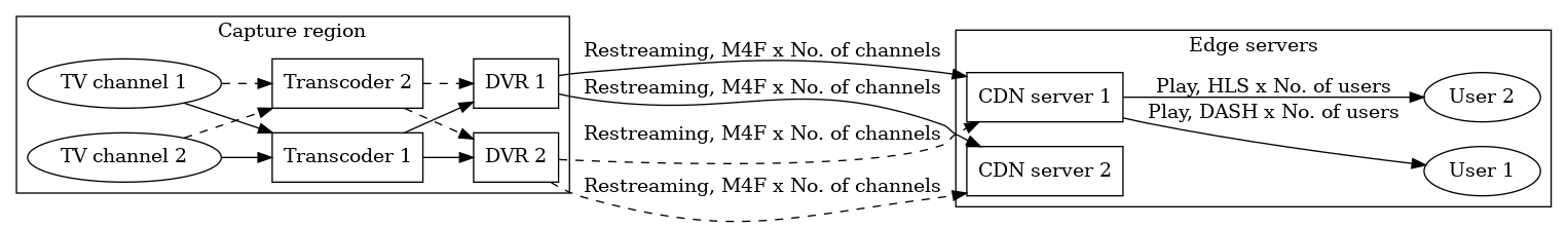
Using this scheme, we will show Flussonic's capabilities.
See also the detailed article about video pipeline in our blog.
Ingesting and transcoding
Various configurations may be made for ingesting streams depending on whether the video may be taken from the source several times, or not. In the easiest case, if you have a video coming from a headend in a multicast via UDP, you can just configure the capturing of the same video on several servers (see Multicast Receiving). However, we will consider the example with cluster ingest which is good for capturing from a source with an expensive/slow connection.
To make sure clients with different bandwidth receive the video sustainably, you have to transcode the video to a multibitrate stream. Thus, the users will be able to select bitrate (i.e. quality) that will be suitable for them. You can transcode on the ingest servers or dedicate a separate pool of servers for that. It depends on the available resources because transcoding is a resource consuming process. In our example, we will perform transcoding on the ingest servers.
We will configure a pool of two transcoders (transcoder1.example.com and transcoder2.example.com) that backup each other using the cluster ingest mechanism:
Transcoder 1
cluster_key mysecretkey;

# Remote sources:
peer transcoder1.example.com {}
peer transcoder2.example.com {}

# Ingest streams:
stream tvchannel1 {
  input udp://239.0.1.1:5500;
  transcoder vb=2048k preset=veryfast ab=128k vb=1024k preset=veryfast ab=64k;
  cluster_ingest;
}
stream tvchannel2 {
  input udp://239.0.1.2:5500;
  transcoder vb=2048k preset=veryfast ab=128k vb=1024k preset=veryfast ab=64k;
  cluster_ingest;
}
Transcoder 2
cluster_key mysecretkey;

# Remote sources:
peer transcoder1.example.com {}
peer transcoder2.example.com {}

# Ingest streams:
stream tvchannel1 {
  input udp://239.0.1.1:5500;
  transcoder vb=2048k preset=veryfast ab=128k;
  cluster_ingest;
}
stream tvchannel2 {
  input udp://239.0.1.2:5500;
  transcoder vb=2048k preset=veryfast ab=128k;
  cluster_ingest;
}
Here and further on, we agree that the servers have correct hostnames that can be resolved.
All the servers should have the same cluster key. In our example it is mysecretkey, but it could have any value.
Note that the configuration is completely identical on both servers. This is a requirement of cluster ingest mechanism: all streams must be declared on all servers.
DVR recording
The servers on which the archive is stored are called origin servers (origin1.example.com and origin2.example.com). In our example those servers restream the video from the transcoders to the CDN edge servers while recording an identical archive so that a backup copy could be accessed if one of the servers fails.
DVR 1
cluster_key mysecretkey;

# Remote sources:
source transcoder1.example.com {
  dvr dvr/origin1 2d;
}
source transcoder2.example.com {
  dvr dvr/origin1 2d;
}
DVR 2
cluster_key mysecretkey;

# Remote sources:
source origin1.example.com {
}
source transcoder1.example.com {
  dvr dvr/origin2 2d;
}
source transcoder2.example.com {
  dvr dvr/origin2 2d;
}
With this configuration, Flussonic will pick up all the channels from one or another transcoder and write them locally to the archive.
Distribution
The CDN servers will act as restreamers retranslating all the streams from the previous link in the pipeline (DVR servers in our case) and caching the recent requests to the DVR:
CDN server 1
cluster_key mysecretkey;

source origin1.example.com {
  cache /storage/cache 2d;
}

source origin2.example.com {
  cache /storage/cache 2d;
}
CDN server 1
cluster_key mysecretkey;

source origin1.example.com {
  cache /storage/cache 2d;
}

source origin2.example.com {
  cache /storage/cache 2d;
}
The restreaming mechanism implemented by Flussonic Media Server ensures that each stream is transmitted to each edge server only once.
The requests to the archive are transparently routed to the corresponding DVR server while the edge servers act as proxy servers. The received videos are cached on the edge servers. Thanks to the cache, subsequent requests for the same content are served faster. Read more about cache here. See also Cluster DVR to learn more about accessing the archive in a distributed video delivery environment.
Since the CDN is the last node in the pipeline before delivering streams to clients, you can add the authorization here and/or define the list of allowed countries.
Scaling the CDN
In case of distributing a large amount of video content, you will probably have several CDN servers in each distribution region so there will be a need for load balancing. In that case you should configure a Flussonic's load balancer in each region like that:
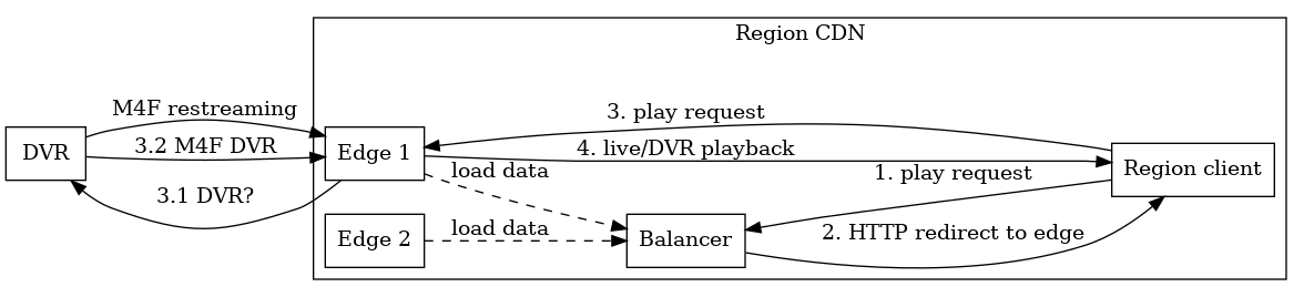
The diagram shows how live video is being restreamed from the DVR server, and the archive is also transmitted when the user accesses an uncached DVR. The clients receive all the video from the edge servers and do not know about the existence of DVR and other pipeline links; the balancer only performs redirects, i.e. video is not streamed through it.