The PCI Express link is shared by a card's ports. Reduced electrical width lowers available bandwidth but does not by itself mean the current capture has failed. The load comparison and operator actions are described below.
Capture cards
The Capture cards section answers the questions that used to be answered by reading the config and walking over to the server room: which cards are installed in the machines of the cluster, how many ports they have, what signal is on those ports, which stream has already taken them and whether a card is overheating.

What is shown about a card
| Column | Meaning |
|---|---|
| Node | the streamer the card is installed in. The section shows the whole cluster |
| Model, Serial number | as the card names them. The serial number is the key by which the card is addressed in a stream's configuration |
| Bus | the PCIe address, and under it the link to the card: width and speed |
| Firmware | the firmware variant: it is what defines the port layout |
| Temperature, Fans | readings from the card's sensors. The section passes no thresholds and no "it is hot" judgement — that is the monitoring system's business |
The PCI Express link is marked as downgraded when the card sits in a slot with fewer lanes than the card itself supports. The link is shared by all of the card's ports, so it sets the bandwidth limit for all of them at once. A downgraded link does not disable any port; it reduces the number of streams the card can deliver. One 2160p50 stream takes about 1.1 GB/s: an x4 Gen 3 slot carries about 3.5 GB/s, that is three such streams, an x4 Gen 2 slot carries half of that, that is one.
The firmware variant defines how many channels the card has, which of them are inputs and which are outputs, and what runs on them: SDI or ASI. In the screenshot the DTA-2178 is in the "2x (12G-SDI+3G-SDI/ASI) with Genlock" variant: of its eight channels, ports 2 and 5 are inputs, ports 1 and 6 are outputs, and the other four are internal outputs. Another firmware variant would lay the same eight connectors out differently, so the direction of a port cannot be derived from its number. The full list of variants for each model is in the DekTec documentation.
The firmware variant cannot be changed from the interface: it is a reflash of the card with the DekTec utility and a power cycle, and capture on every port of the card stops for the duration.
Ports
A card row expands into a table of its ports.
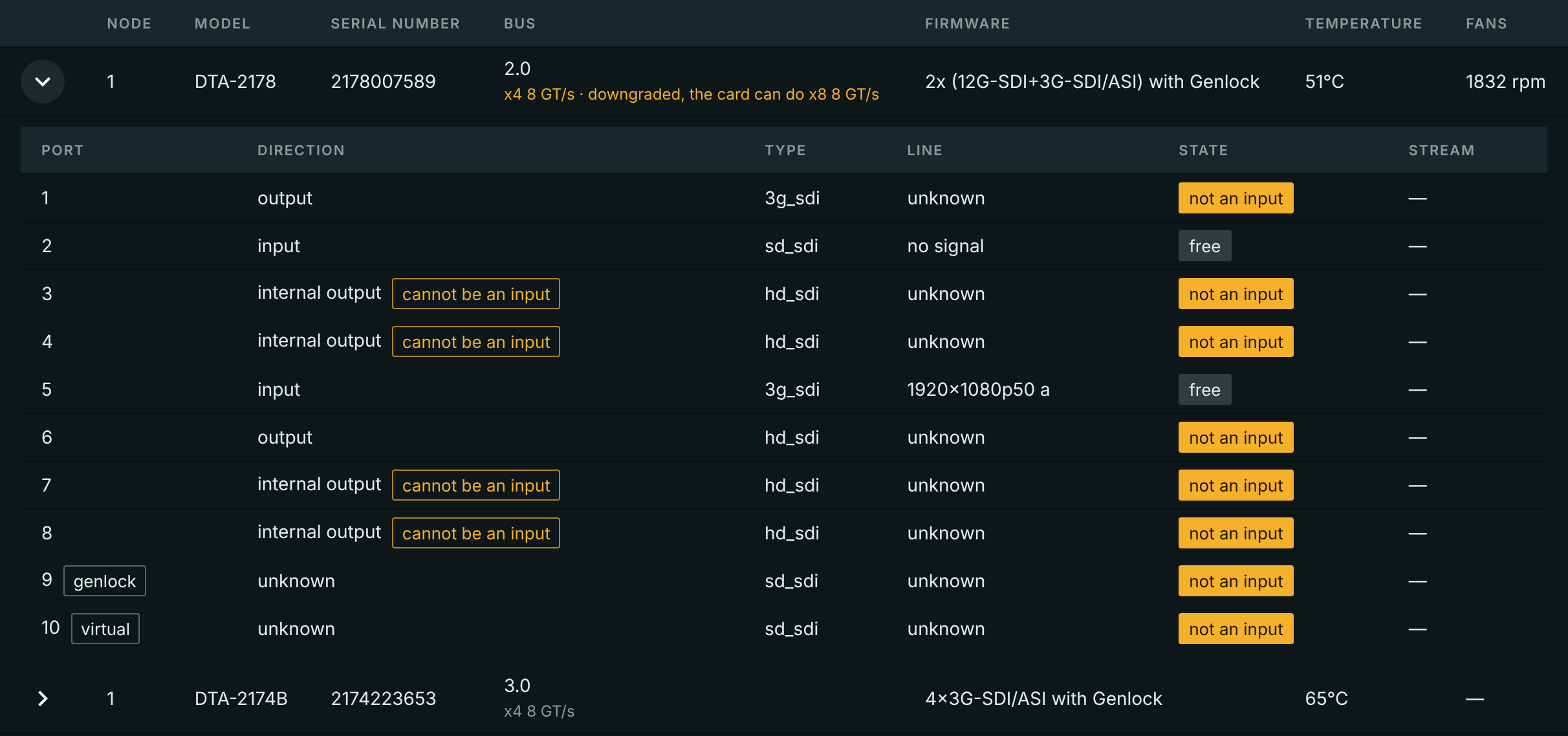
A port's state is named with a word from a closed vocabulary, because behind every word stands a different action for the operator:
| State | What it means | What to do |
|---|---|---|
| not an input | the firmware variant made the port an output or a port of another type | move the cable or reflash the card |
| free | an input port not assigned to any stream | it can be assigned |
| assigned to a stream | an input port named in the streamer's applied configuration | nothing; the stream name is next to it as a link |
| held by a wedged process | this port's capture process exited neither on stdin close nor on SIGKILL |
this is dealt with on the host |
| held by an outside process | by firmware the port is an input, by our table it is free or ours, and capture answers "port busy" | look for the outside holder |
| state this version does not know | the streamer is newer than the panel and named a state the panel has no word for | do not assign a stream — the port may well be busy; update the panel |
There is no generic "busy" in the section: every state has its own action, and the table names it.
Direction stands apart from state. The "cannot be an input" mark next to it says not what the port is busy with now but that the firmware variant did not make it an input. A plain output carries no mark: the firmware can switch it to an input. An internal output always carries it: the firmware has given it to a neighbouring port. Only a reflash changes this, see above.
Two kinds of ports take no signal at all and are not always represented by a connector on the bracket:
- genlock — a reference input: the card takes its reference signal there, not a signal to record;
- virtual — there is no connector at all; with it the card exposes its own free-running reference, that is, the state of "not locked to anything".
The Type column shows what kind of signal the port is set up for right now: sd_sdi, hd_sdi, 3g_sdi or 12g_sdi. This is a setting, not the port's limit: a free port keeps the last value, and once a 12G signal is fed into a port showing hd_sdi the type changes by itself.
The Line column says what the card sees on the port right now:
- a resolution and rate — there is a signal, and this is what it is. The letter after the rate is the 3G signal level, A or B;
- "no signal" — an input port on which the card sees nothing;
- "unknown" — the card reported no line state. Outputs, genlock and the virtual port never have one, and it does not mean an absence of signal.
If the card scales the signal itself (takes 12G and hands 3G upstream) or detects a kind of signal on the line other than the one the port is configured for, that is marked with a hint next to it. Without such a mark a mismatch between the standard on the line and the stream's resolution reads as a defect that is not there.
The port and the stream are linked both ways
From a port row a link leads to the card of the stream that took it. The reverse link — "Show in capture cards" — sits in the stream's input section, next to the serial field.
The card and the port are also picked from there: the fields of the SDI (DekTec) section take their values from this very inventory. See SDI ingest for details.
The assignment is checked against the firmware, but the configuration is not rejected for it: it has to apply both before the card is installed and on another streamer. A stream assigned to a port that is not an input in the latest snapshot gets that fact into its input statistics. That is what explains a "port busy" failure with no process holding the port.
When no cards are shown
The section tells three different kinds of "empty" apart, because the actions differ:
- There are no cards. The probe succeeded and there were no cards in the machine. Such streamers are not listed at all.
- The inventory is unknown. The probe failed. The streamer is listed as a separate row with the cause and the age of the last successful probe.
- The streamer is unreachable. There is no contact with the streamer itself. Also a separate row with its own cause.
The failure of the probe is named by a cause of its own:
- not installed — the
dektec-bridgepackage is absent from the host; - timed out — the probe did not finish within its timeout;
- exited with an error — a non-zero exit code;
- unparsable answer — the output could not be read;
- a reason this version does not know — the streamer named a cause the panel has no word for.
The data is taken by dektec_probe — a one-off call, not a daemon: the streamer runs it once a minute, reads JSON from its output and lets the process finish. The probe opens no ports at all, so it cannot disturb capture. It is installed by the dektec-bridge package next to dektec_ingest; the package being absent from the host is a normal state, in which the section says "inventory unknown" rather than showing an empty park.
What goes to monitoring
Three series go to Prometheus: capture_card_info with the card's static facts in labels, capture_card_temperature_celsius and capture_card_fan_rpm. The joining key is the serial number, not the bus address: a card gets moved to another slot, and history keyed by bus/slot would be cut although the card is the same.
Temperature and fan speed go to monitoring at all times, not only when the values are alarming: a series that appeared only on overheating could not be told apart from missing data.
A passively cooled card has no fan series at all. That is not zero rpm: "there is no fan" and "the fan has stopped" are different things, and they must not be confused.
There are no series for ports: their state does not change between scrapes and raises no alerts, while the line state of a busy port already travels from the stream's side.
Reading the PCIe indication
The Bus column lists the card and upstream PCIe port addresses. Each link shows its current speed and width, followed by its maximum values in parentheses. 8 GT/s ×4 (max 8 GT/s ×8) means four active Gen3 lanes on a link supporting eight: the physical size of the motherboard connector does not determine the electrical connection.
Below the links, Video capture / PCIe limit, active inputs describes active capture, not every configured stream. GB/s means gigabytes per second, not gigabits.
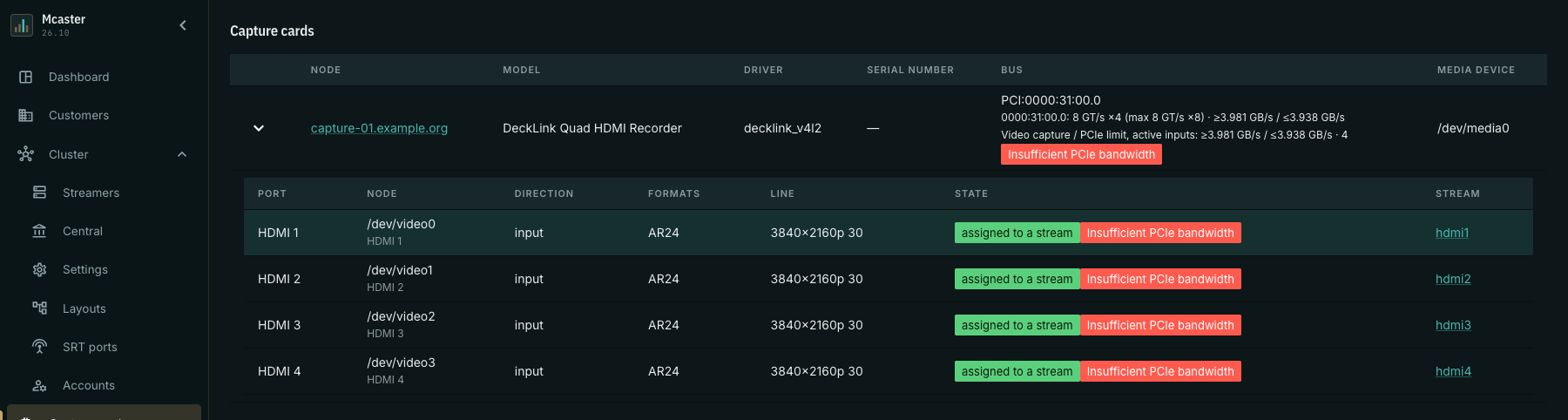
- Insufficient PCIe bandwidth — the calculated load of active captures already exceeds the physical limit of at least one link. The card and its active inputs carry a red indication.
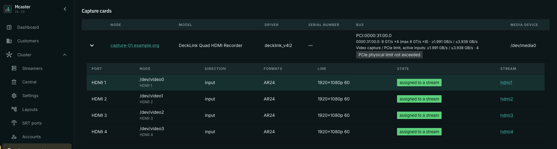
- PCIe physical limit not exceeded — available data shows no excess. This does not guarantee healthy capture or available bandwidth.
- Bandwidth unknown — data is insufficient for a current verdict or the snapshot is stale.
The input card on the stream page also shows a red PCIe indicator and a Total load / PCIe capacity link to the capture cards section. This error can appear while frames still arrive. “Assigned to stream” in the port table describes assignment, not video health.
Video load is a lower bound (≥); PCIe capacity is an upper bound (≤). The calculation uses the transferred frame size, including row stride, and frame rate. This is uncompressed video between the card and memory, not the output H.264/H.265 bitrate. Capacity depends on the current link and upstream port limits; known active capture loads are added on a shared port. Audio, PCIe overhead and other devices reduce headroom.
Example: four HDMI inputs
The demonstration screenshots show a DeckLink Quad HDMI Recorder with four active inputs and a Gen3 ×4 link. They show the real UI with fixed API snapshots, not a measurement of a production installation's current state.
For Gen3 ×4, the upper bound after line encoding is 8 × 10⁹ × 4 × 128/130 ÷ 8 ≈ 3.938 GB/s. Here the card transfers ARGB, four bytes per pixel, with no extra row padding.
Four 3840×2160 captures at 30 fps require at least 4 × 3840 × 2160 × 4 × 30 = 3,981,312,000 bytes/s, or 3.981 GB/s. This exceeds 3.938 GB/s: the card and all four inputs show an error.
Switching all four sources to 1920×1080 at 60 fps reduces the load to 4 × 1920 × 1080 × 4 × 60 = 1,990,656,000 bytes/s. The UI rounds this to 1.991 GB/s. The red indication disappears and “PCIe physical limit not exceeded” appears.
The signal and format are explicit in this example: these numbers do not apply to a different pixel format, row padding or frame rate.
Resolving insufficient bandwidth
- Follow the link from the input card and check the active link, capture count and signal format.
- Reduce the source's actual output signal resolution or frame rate, or stop unnecessary captures sharing the bus. Windows desktop resolution can differ from “Active signal mode”: reducing only the desktop does not reduce a 4K HDMI signal.
- If the original mode is required, move the card to a slot with sufficient electrical width and check the upstream PCIe ports. Shut down the server following the manufacturer's instructions before moving the card.
- Reload the capture cards page after statistics update, confirm the error disappears, and separately check video and stream input errors.
Reducing transcoder bitrate does not reduce uncompressed frame transfers over PCIe. The red indication neither changes source settings nor stops capture automatically.
When data is incomplete
Unknown link speed or width, a missing active capture format, or data from an older streamer do not mean bandwidth is sufficient. When a streamer becomes unreachable or probing fails, inventory may remain visible, but an old red port indication is no longer presented as a current error.
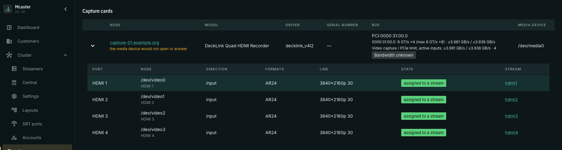
Restore connectivity or resolve the probing failure, then obtain fresh statistics. Reinstalling a driver is not a universal solution to insufficient electrical PCIe width.